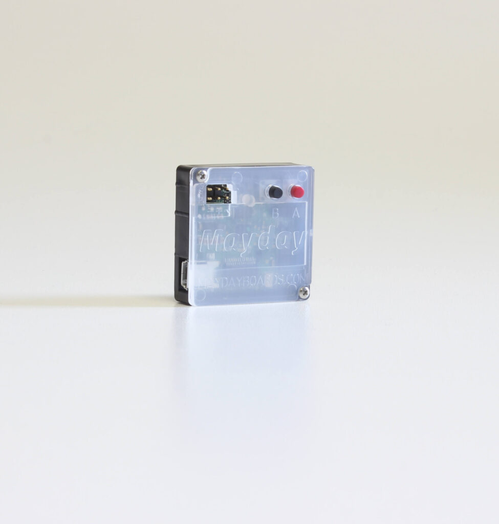
Electronic monitor for a homebrew keezer.


Keezer-meter
11-8-2019
I’m happy to say I have bought a new freezer to replace the broken keezer it is smaller and only holds 3 kegs instead of 4 but the overall outside dimensions are much better for the limited space in the garage. More importantly the freezer has been converted and is running a kezzermeter and controlling the temperature wonderfully. Since the last post a lot has happened sticking to the things that affect the keezer meter firstly my frezzer stopped cooling and with no way to cool beer I lost a lot of my intrest in brewing and consequently the keezer meter. I also spent many hours working on a radio product that sends a small amount of data a long distance. In the setup of the new kezzer I realized the hardships of using usb cables to connect to the board and started wondering what it would take to do wireless module, battery, cost, etc. so I did some googling and found a TI micro controller that runs on very low power and would be good for a battery. Introduce TI Launchpad and while I was able to get this running and read the load cells it seemed slightly overkill still and unfamiliar. I dug threw some old hardware and found an attiny85 this little chip seemed to fit the bill for cheap small and low power. And while this chip can get to very low power it did that by sacrificing clock speed. I don’t mind a low clock speed but I also don’t want to write a library to handle ASK protocol when a 8mhz will do ok, and back to the 328p I go. Handily I have been using the low power chip this whole time the p at the end of the 328 actually denoted a version of the chip specifically designed for low power use. So to recap a bit the new goal is to remove the 8 USB ports on the keezermeter and replace it with 1 wireless receiver using an ASK protocol. The scales will then also be wireless and battery powered. And the plan for the scales is as follows:
Same 4x half bridge load cells
Hx711 chip pulled from the cheap boards and placed on the new board (explanation later)
A cr2032 battery
Atmega328p
A button or just to solder pads
An ASK transmitter
And the minimum passive components
I will address each point in order. The load cells are still the cheapest option and have a great range for the resolution. The hx711 chip seems to be quite unique that it is a ic specific to loadcell and scale use other op-amps and adc simply require more development and may still not be as good from my experience early on with the ad466(need to double check pn)’s. the reson it needs to be pulled from the $1 china pcbs is the pcb does not allow to change the operation mode of the ic 80hz vs 10hz. I have done quite a lot of testing on the system so far and the cr2032 seems to last a long time anywhere from a few months to a few years. The battery is tiny and while not rechargeable shold be ok as most people will probably never need to replace it. The main micro controller the atmega328p. as I discussed earlier this chip just seems to be capable of it all it also allows for a slightly simpler BOM. I button or pads are needed just so the initial setup of the scale can have a unique identifier. the scale will need to be assigned a number 0-255 and the button press that many times when the scale is powered on. This will then be saved and not need to be done again. This number will be used when sending the information the keezer meter to know what scale send the data. The ASK TX is the new most aspect changing part and yet seems to operate so simply. Its low on power cheap uses only a few passive components(6) and is really tiny. The minimum supporting components is the most recent work I have done on this. I made 3 different modules 1 for the tx 1 for the hx711 and 1 for an atmega parts were soldered on and tested with plans of removing part 1 or 2 at a time to see if they were really required for the circuit mostly caps and some pull up or pull down resistors. Unfortunately likely so to not hot air soldering the atmega it shorted out on both test boards. So the next step will be to rectify that experiment and continue until the scales are ready for a single pcb design and maximum power saving code can be started.
11-13-17 libraries for Arduino code cp2102 usb driver
Arduino-Temperature-Control-Library-master
Arduino-Temperature-Control-Library-master
HX711-master
MemoryFree
OneWire-master
Si7021
10-27-2017 I have tested the new PCB’s and everything is working fine. I have added them to the shop HERE. I will add more documentation soon about settings and lcd screens. I am also making progress on an iphone app and will post info when it looks a little nicer.
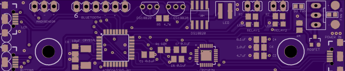
9-18-2017 I just got the PCB’s today for the Keezermeter 3.0. Most of this post will discuss the Bluetooth module and settings. I did have a trace running from GPIO2 on the Bluetooth module to reset to hopefully be able to upload programs in the future but it was interfering with the USB capability to reset on arduino upload. So I had to cut the trace but this may still work if I can get the Bluetooth GPIO2 pin to not leave the pin pulled high on reset. I will make an update if I get that resolved the trace can also be cut easily to fix the problem. I removed the trace and sent files out to get a price on the PCB I will Sell them in the shop as soon as I get them and test one. The Bluetooth module has a few useful commands that can be sent from the usb port. “AT” Just sends back OK to confirm its working “AT+MODE2” lets the Bluetooth be in the AT command mode threw the Bluetooth interface “AT+NAMEKezzermeter” sets the name to Keezermeter “AT+SHOW” displays the name during discovery “AT+TYPE” follow with a 0,1,2,3 different pin code interactions might be needed for android devices apple work with default I will Post more about the updated PCB and version 3.0 When I have some more time to play with it.
9-11-17 Keezermeter 3.0 UNTESTED If all goes well with this revision I should have components and systems up for sale in a month. Changes to rev 3.0 include. -cp2102n from 5×5 package to 3×3 package. Its cheaper smaller and seems to be in stock more often. -3 ds18b20 ports instead of 2 -HM-11 serial traces moved to dedicated lines. Both bluetooth and usb can be used and control eachother. -button added to pcb. Primary functions are to turn on led lights and use LCD -removed ground plane from si7021 and added holes -replaced crystal with resonator. the resonator is slightly less accurate at keeping time but is cheaper smaller and 1 component compared to 3. -added a boost ic for fan. 5v usb input now powers a 12v fan at 12v up to .3 amps
some of the pins have been moved around such as the relays to make pins available for the bluetooth. I will post new code to adjust this and handle new hardware. The BOM includes almost all optional parts except lcd, fan and scales. Some parts such as hm-11 bluetooth and ds18b20 sensors can also be purchased from eBay usually at a lower price.
8/18/17 KeezerMeter Arduino code
8/17/17 Project Info. Below are the eagle files, Bom and a link to OSHpark for the pcb. The bom does not include hm-11 bluetooth module or the proximity sensor. It also does not include the external components such as ds18b20 temp sensors or hx711 modules(scales).
keezerMeter EAGLE files
4/24/2017 Board files are done and sent to fab. I am having a hard time finding a good LED to fit the bill, I wanted to use cree but cant find any that are warm white or any warm white for that matter. The rest of the board is sourced for parts the only thing I would change is the ds18b0 the chips are about $2 each even the micro controller is cheaper. I should have the boards back and populated in 2-3 weeks. although I have plans to make a buttons PCB I may wait until this revision works. From the picture you can see where things go.
4/19/17 Schematic is mostly complete with the exception of a few data pins a may switch while routing the board. I have done away with any voltage boosting for the fan there are 2 jumpers, 1 for 5 volt and 1 for input voltage probably 12 or 24 volts. pcb has 1 surface mount temp sensor and space for 2 extra threw hole sensors. 2x M3 mounting holes 2.5″ apart, .5″ from top and bottom.
4/3/17 Today I tested surface mounting all the parts needed for the kezzer-meter and using the cp2102 for usb to uart. I will probably do this as others want the board assembled. When I do finish this project the current idea is to sell boards, kits and 90% complete
DescriptionUnitPriceUSDExtendedPriceUSD321727-4925-1-NDMOSFETN-CH30V1.9ASOT230.631.26410609-4613-1-
systems as well as post board and code files for others to expand on the design. the 90% boards will have all surface mount parts attached and no though hole mount parts soldered such as a proximity sensor fan connector and so on (easy to solder stuff). later I will test the fan boost circuit and see if the usb has enough power for it. With a raspberry pi able to suck so much power threw a micro usb i’m hopefull.
3/13/17 Long time no post. I started a job the day after my final for C++ and did not have time to work on it. I will be altering the board a bit, the picture below outlines the devices attached to the arduino micro controller. Scales will be attached threw a usb cable, fan will be powered by a separate USB 1 amp power block but will no longer require a cpu fan with integrated pwm it will now be externally controlled with a boost ic and transistor. I will be writing a windows app for a user interface to be ran on a tablet or the 16×2 lcd and buttons can also be used. the LCD would now be remotely attached(i2c) as will the buttons. Also adding proximity sensor and led so the when you open the door the light comes on will probably add optional time out and always on functions. i will add a bluetooth chip for future app controlled setup but i dont know how to write ios and android apps
5/11/16 I will be rewriting the code in a few weeks for the keezer-meter and will make it easier to modify for everyone’s application. I am happy with the hardware and have sent out for some acrylic scales to be cut I should have about 10 extra plates that need the hx-711 fixed and loadcells fixed to them. I will add them to the shop when they arrive.
2/12/16 Quick update. The latest boards arrived and 2 have been populated some initial problems have been solved as how to read temp sensors without waiting .75 each time. Also how to check what scales are plugged in. I started the code from scratch do to the # of changes that needed to be made and the increased time it takes to read the sensors. The menu will still operate in the same way but will now allow for sensors to be read during the sub menus. I did this do help with controlling and offsetting the drift. The scales seem to be quite sensitive reliably reading 1oz
increments of fluid. The latest board design has micro usb ports added to the traditional pin outs of scales the were not the easiest thing to solder so if anyone else not proficient soldering small pins should use the .1 header pins. I will Post a video soon of the info and using the menu.
1/12/16 my second HX711 arrived last night and I hooked it up everything seems to work as planned. I will be using 5 hx711 boards, 1 on each scale they will have a 4 wire SPI interface to the arduino via the PCB with the 6 pins available on the arduino I will have 1 common input SCK pin and 5 output pins. I will be running jumpers on the PCB that I have to make a prototype of this setup. I also estimate 4 readings per second on all scales so I can add some averaging to the raw output data. I do have 6 new HX711 chips on there way from china but do not expect them for a couple weeks. The scales now will consist of a plate made of acrylic with 4 load cells and the HX711 they will cost about $10 in materials. the PCB will cost 3 for $20 the components will cost $10 per PCB So for a kezzer with 4 kegs and a co2 tank the cost would be about $80. I will try to make the PCB’s in china and make enough for others to buy bring the cost down to $11 + $10 for each scale. There is also an added benefit to using the HX711. The SPI pins will be used as digital pins allowing me to use the 1.1v internal analog reference. This helped the accuracy of the temp sensor greatly. I will try to add some more pictures on progress soon.
1/6/15 The pcb’s arrived from oshpark but I am not happy with the amplifiers that take the signal from the scale and send it to the arduino. This lack of resolution may also be caused by the 10bit ADC in the arduino. The solution seems to be the hx711 module. This module will be on the scale side decreasing the size of the pcb and saving cost since the modules are only $1. The module hosts an amplifier for the scale as well as a 24bit ADC. The main problem with using this chip is the SPI bus that communicates with to micro controller the SPI bus requires 2 pins one input to send commands like power up, power down, set gain, start data transmission and one output to know when data is ready and receive the 24bit value.
Early tests look good with this chip. It looks like I can read changes in 1oz reliability. This will help a lot when characterizing the “drift” I am told about. The only problem with using the hx711 will be communicating with 5 of them. I may have a way to use 5 and read them separately but this will require 10 pins and with all the things I added we only have 6. One idea I have is to use 1 common input pin and 5 separate output pins. This will send the read command to all 5 outputs and only look to one at a time. One example reads the value twenty times, averages the number and serial prints the value this takes only a second or two. the only other space I can find pins are the 3 buttons. All 3 can be moved to 1 analog pin but I will still only have 8 pins not 10.
12/15/15 I have sent out the next order for pcb’s. This time I used oshpark for the faster turnaround time. The boards end up about $10each instead of $3 so if I don’t need more than one I will post the other 2 for $10 each this board has the relay output, 6th scale, 2nd temp sensor, fan pinouts, relocated contrast trim pot, header pins for power, 3.3v power for temp sensors, a button for the sub menu, and decreased overall size. I have also populated one of the boards from iteed.
11/30/15 After some feedback I have created a sub menu for programming abv gravity and names.I finally received the pcb’s that I ordered from china and they are exactly what I asked for. That said is has been some time and i have made multiple revisions to where the code I am working on will not function on this PCB. it is nice to know the turnaround time and quality of the pcb’s.
11/09/15 Yet another revision this time I used the rest of the analog pins and the last digital pin still allowing for serial communication. There are now 6 locations for scales and 2 locations for temp sensors 1 on the board and 1 set of headers for another to be dropped to the bottom of the kezzer. This was to check for temperature differences so the fan will not need to run all the time. The digital pin is pin 13 the pin pre-connectod to an led. According to the solid state relay I will be using on this pin it will only need 7.5mAh. This relay will be used for temperature control of the kezzer, not something I originally intended to do but that last pin being empty was bothering me and why not have digital temperature controller. The voltage divider for the amplifiers needed to be moved to make way for the 4 pin (pwm) fan connector it is now close to the power input and will only work if the power to the board is equal to the voltage of the fan usually 12v and is powered through the pcb not the usb. Sorry but there will not be a way to read the rpm’s of the fan as both interrupt pins are in use for the lcd. the solder pads on the pcb for power have beed moved to the back side in case the wires need to be replaced at some point. .1 headers have also been added around the solder pads to make a removable power connector. The overall boards size has been reduced a little about 1/8″ to 1/4″ in each direction. After routing the traces I found some information on the tmp36 and problems using it on the 5v rail with other components mostly relays. The fix seems to be to move the temp sensor to the 3.3v rail. Bringing down the AREF on the arduino nano from the default 5v to 3.3v even 1.1v in this case as we do not need +60C temp measurements would greatly increase the accuracy of the sensor interpretation. This may not work as It will affect the range of the instrumentation amplifiers and if I remember correctly they were using about 3-4v, outside of the 3.3v range. It may still be possible with a different voltage divider or negative power source and I will be looking in to that.
Features 6 scale headers for keg or tank volume monitoring 2 temp-sensors 1 fan (pwm) control of speed calibration of all kegs or tanks eeprom memory to store calibration values, fan speed, temp setting lcd display beer information (manually entered) 1 relay header for temperature control estimated cost less than $50
11/4/15 I had an extra pin on the pcb and decided to add a pc fan with speed control assuming a 4wire fan is used a 3 wire can still be used but will run full speed. The fan will require that the pcb has a 12v power source. I don’t think I will add a regulator to the board since a little psu is only $3 and will most likely be the psu of choice. I am also changing the calibration mode jumper pins to a button on the back this is also the button pressed to allow the fan speed to be changed and to lock it again. The trim pot for contrast of the LCD was originally under the nano so that I could router a prototype and is a really inconvenient location. That has been moved to allow access.
10/30/15 load cells have arrived and board has been sent to board house turnaround time looks to take 3 weeks. Boards were purchased form www.itead.cc under the 5cm x 10cm. total after shipping for 12 boards was $18.90. Here are the current gerber files and code if anyone wants to try it.
download Gerber files krashkeg.zip 74.9 KB
download arduino code krashkegcode.zip 2.98 KB
10/14/15 3 more sets of load cells ordered for the kegs and a 10KG load cell for the CO2 tank but 30-45 day shipping.
10/7/15 Prototype of the final board is done and working. I will now be ordering more load cells for the kegs and a more sensitive load cell for the co2 tank. I will also soon 3d print a frame for the lcd that will be let in to the front of the keezer.
9/20/15 Code is not fun, yet Progress has been made. The current design of the project will use an arduino nano instead of a atmega328p DIP. This will simplify the parts list a bit and make reprogramming at keg changes easier. I will be using female header pins, so the nano can be removed quickly. The nano clones are also extremely inexpensive- around $3. Being able to use USB with the built-in FTID chip is another benefit to using the arduino nano. This design also has 2 buttons to navigate the menu pages. The menu pages include 4 beers, a CO2 tank, and a temperature page. All pages, except the temperature page, can be navigated to a calibration mode by shorting a jumper on the board while in the page you want to calibrate. The Calibration will be using load cells under each keg and CO2 tank to display how much beer or CO2 is
left in the keg or tank. The calibration asks for a wet and dry weight and lets you know that the values are saved. These values are saved to the EEPROM (non-volatile memory ) in the arduino nano, so even when unplugged – to reprogram beer names – the Calibration values will remain.
I purchased an lcd shield to start working on the code. Initial results look promising and already thinking about expanding to more sensors and a larger readout.
New project the Keezer-meter. I know a few of these have been done but the arduino based ones I have seen have all used flow sensors to determine the quantity of beer left in the kegs. I would prefer to use scales so that i would not have to calibrate the initial volume in the keg in the case that not all my batches produce exactly 5 gallons. Most of the schematic is ready to go just waiting on parts to run a breadboard test.
The Keezer
The First batch of beer!